
This guide explores various types of pneumatic valves, including solenoid and directional control valves. Learn their applications and how to select the right one for your needs.
What Are Pneumatic Valves?
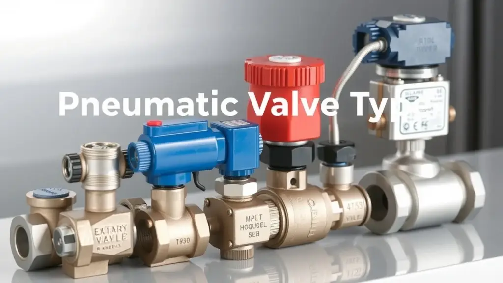
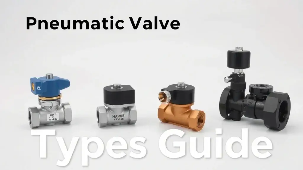
Pneumatic valves control the flow and direction of compressed air in industrial systems. They play a key role in pneumatic systems, allowing machines to function properly. These valves help manage airflow for tasks like moving cylinders, controlling pressure, and ensuring safety. By regulating compressed air, they boost energy efficiency and reliability in various applications.
There are several types of pneumatic valves. Some common examples include solenoid valves, pilot-operated valves, poppet valves, diaphragm valves, and spool valves. Each type has specific uses within a compressed air system. Whether it’s a simple on/off action or more complex flow regulation, these valves are vital for smooth operations in modern manufacturing.
Why Understanding Valve Types Matters?
Knowing about different pneumatic valve types is important for making the right valve selection. Choosing the wrong type can affect how well your system works and might lead to problems down the line.
For example, picking an unsuitable valve can cause low flow rates or improper pressure control. This could harm equipment or lead to higher energy costs. By understanding the benefits and drawbacks of various pneumatic valve designs, engineers and technicians can make better choices that improve maintenance plans and operational efficiency.
When professionals grasp how each valve works—like its main function and materials used—they can find the right solutions for their needs. This knowledge not only enhances productivity but also ensures long-term reliability in automated systems.
Core Types of Pneumatic Valves Explained
Solenoid Valves
A solenoid valve is an electromechanical device that controls air or fluid flow in a pneumatic system. It has three main parts: a coil, plunger, and valve body. When electricity flows through the coil, it creates a magnetic field. This field moves the plunger to either open or close the valve, allowing precise airflow control for various applications.
Key variants of solenoid valves include:
- 2/2-way Valve: This type controls flow between two ports and can be normally closed (NC) or normally open (NO).
- 3/2-way Valve: This one directs airflow from one source to two outputs. It’s often used with single-acting cylinders.
- 5/2-way Valve: This valve manages airflow for double-acting cylinders with multiple positions.
These configurations are crucial for directional control in pneumatic systems.
Solenoid valves find applications across various industries like robotics, packaging machinery, and process control systems. In robotics, they enable quick movement adjustments. In packaging machinery, they help in efficient sealing processes. For process control systems, they ensure accurate material regulation.
The benefits of using solenoid valves include their fast response time and easy integration into automated systems. However, they do have downsides; being power-dependent means a loss of electricity can cause operational failures.
Pilot Operated Valves
Pilot operated valves use a small pilot signal to control larger flows within pneumatic circuits. The mechanism typically involves direct acting components where pressure differences activate the main valve based on signals from smaller actuators.
Common configurations include:
- Two-Port Configuration: Allows flow through one inlet and one outlet.
- Three-Port Configuration: Diverts flow between two outlets.
- Four-Port Configuration: Offers more complex routing options for advanced applications.
These types are especially useful for precision control situations where low energy consumption is needed because they work well at lower pressures compared to direct acting counterparts.
Typical use cases involve scenarios requiring high accuracy without excessive energy use. These valves are perfect for automation tasks that focus on efficiency.
Pilot operated valves provide better precision and lower energy costs as advantages. However, their slower response times compared to solenoids may limit their use in some situations.
Manually Operated Valves
Manual actuation methods include devices like lever-operated ball valves and butterfly designs that require human action to operate. These mechanisms are straightforward and fit well for simpler tasks where automation isn’t needed.
Best-fit scenarios include emergency shut-off systems where immediate manual access is critical or low-cost solutions during budget constraints without sacrificing reliability.
The main benefit is simplicity; manual operators are generally easier and cheaper than automated options. However, this simplicity comes with limitations like the lack of automation features which can reduce operational efficiency when quick responses are necessary during dynamic processes.
Foot Pedal Controlled Pneumatic Valves
Foot pedal controlled pneumatic valves offer hands-free operation by letting users engage them via foot pedals instead of hand controls. This design improves safety and convenience when both hands must be free during operations involving heavy equipment or detailed assembly lines.
Industries benefiting from these options vary widely—from medical facilities using them in surgical environments to maintain sterile conditions while keeping operator focus—to manufacturing lines improving workflow efficiency by reducing downtime related to manual handling.
Specialized Valve Types
Among specialized types are pressure-reducing models designed for compressed air systems aimed at keeping consistent output pressures across different industrial settings including HVAC installations and automotive braking systems. They play an important role in ensuring stable performance even with fluctuating supply pressures—a key factor for operational integrity across various applications.
Diaphragm mechanisms represent another category defined by flexible membranes that manage fluid passage based on pressure changes applied against them. They are often used in food processing plants since hygiene standards demand practices that prevent contamination while effectively managing materials within those processes.
Solenoid Operated Pneumatic Valves
Solenoid operated pneumatic valves are key parts in many automation systems. They control the flow of compressed air in a pneumatic circuit. These valves work using an electromagnetic coil mechanism that opens and closes the valve. The main types include 2/2-way, 3/2-way, and 5/2-way valves, each designed for specific tasks depending on what is needed.
How Solenoid Operated Air Flow Works?
Solenoid valves operate based on an electromagnetic coil. When electricity flows through the coil, it creates a magnetic field. This magnetic field moves a plunger or armature inside the valve body. The movement changes the position of the valve to either open or close the airflow path.
In pneumatic system design, knowing how this mechanism works is essential for proper integration into automated processes. A well-designed system helps manage airflow effectively while reducing energy use and wear on parts.
Port Configurations
Pneumatic solenoid valves have different port configurations to meet various needs:
- Two-Way Valve (2/2): This type has two ports—one for inlet and one for outlet. It’s mainly used for simple ON/OFF control.
- Three-Way Valve (3/2): This one has three ports. It can direct airflow between two outputs based on whether it is activated.
- Five-Port Valve (5/2): Commonly found in double-acting cylinders, this valve directs airflow to both sides of a cylinder for more complex operations.
These port configurations are vital for managing pressure changes and fluid flow in various situations.
Examples of Subcategories Explained
There are several subcategories within solenoid operated pneumatic valves that increase their usefulness:
- Directional Control Valves: These valves manage the direction of airflow within a system.
- Normally Open Valve: This valve stays open until it’s energized. It’s great for situations where you want constant airflow unless something interrupts it.
- Normally Closed Valve: This type remains closed until activated, making it ideal where safety requires stopping airflow when power fails.
Knowing about these subcategories helps engineers choose the right solutions for specific needs and improves performance across many industrial uses.
Classification of Pneumatic Valves by Functionality
Pneumatic valves control the flow and direction of compressed air in various systems. Understanding the types of pneumatic valves is important for engineers, technicians, and students in industrial automation. These valves can be grouped based on their functionality into several categories: directional control valves, flow control valves, pressure control valves, on-off valves, and regulating valves.
Directional Control Valves Explained
Directional control valves are key parts that manage airflow paths in a pneumatic system. They decide how actuators move by directing airflow to specific ports. Here are some common types:
- Two-Way Valve: This valve has two ports—one for inlet and one for outlet. It can either allow or block airflow.
- Three-Way Valve: With three ports, this valve can direct air to an actuator or let it exhaust back to the atmosphere.
- Four-Way Directional Valve: This type is often used with double-acting cylinders. It controls two actuators at once by providing four distinct paths for airflow.
Solenoid-operated versions of these directional control valves use electromagnetic coils to automate operation. When activated, solenoids shift internal parts that open or close pathways as needed.
Flow Control vs Pressure Control Valves
Flow regulation and pressure management are vital for optimal performance in pneumatic systems.
Flow Control Valves adjust the speed of air moving through a system by changing its passage size. This affects actuator speed without significantly altering system pressure.
On the other hand, Pressure Control Valves keep desired pressure levels within a circuit. They handle variations in input supply or downstream demand. Common types include relief valves that prevent overpressure conditions and regulators designed to stabilize output pressures against fluctuating inputs.
Both types serve different purposes but work together to improve efficiency in pneumatic applications.
On-Off vs Regulating Pneumatic Valves
On-off pneumatic valves provide simple functionality; they either allow full flow when opened or completely block it when closed. This basic mechanism suits applications needing simple actuation without detailed adjustments.
Regulating pneumatic valves offer more advanced features by enabling precise media regulation across varying conditions while maintaining consistent operational parameters like temperature and pressure. Their design allows fine-tuning necessary for processes where exact specifications must be met consistently throughout operation cycles.
Understanding these classifications helps professionals choose suitable solutions tailored specifically to their application needs while ensuring reliability and efficiency in their systems.
Pneumatic Valve Internal Mechanisms
Diaphragm Valves
Diaphragm valves use a flexible diaphragm that moves to control the flow of air or liquid. When pressure builds, the diaphragm bends upward, letting the media pass through. When the pressure is off, it goes back down, sealing the flow. These valves work well in situations needing precise pressure control and fluid regulation, like chemical processing and water treatment. One big benefit is their leak prevention due to their unique design. This feature makes them great for handling corrosive materials that could cause safety issues if leaked.
Spool Valves
Spool valves are important in directing airflow in pneumatic systems. They have a cylindrical spool that shifts between different positions to either allow or block air passage. The configuration—like 2-way or 3-way—affects how actuators move. In industrial automation, these directional control valves are key for managing several actuators at once while keeping operations efficient.
Spool valve designs can include features like spring-return mechanisms or solenoid actuation. For example, a 5/2 spool valve can switch airflow between two outputs based on signals from sensors or controllers. Their adaptability allows them to fit into complex machinery setups where reliable performance is essential.
Poppet Valves
Poppet valves operate with a movable poppet that opens or closes against a seat under various pressures. Usually designed as normally closed devices, they stay sealed until activated by external forces such as pneumatic pressure or mechanical action. This characteristic makes poppet valves ideal for high-pressure applications like safety relief systems, where fail-safe features are vital.
A key advantage of poppet valves is their low leakage rates compared to other pneumatic controls. This ensures minimal loss during operation and improves overall efficiency in pressurized environments.
Piston Valves
Piston valves feature an internal piston mechanism that controls flow rate by moving back and forth inside the valve body according to pressure differences acting on it. They are preferred in situations needing durability under high pressures due to robust construction materials that withstand harsh conditions.
These pneumatic valves are commonly used in steam control and heavy-duty processes where long-term reliability is crucial for success.
Valve Body Styles and Materials
Common Valve Body Styles
Pneumatic valves come in different styles, designed for various tasks within pneumatic systems. The most common types are inline valves and manifold mounted valves.
Inline Valves: These valves fit directly into the flow line of a pneumatic system. Their design allows for easy installation and maintenance. This makes them perfect for situations where space is tight or easy access is needed. Inline valves provide direct control over airflow, ensuring efficient operation.
Manifold Mounted Valves: This type groups several valves together on one base plate or assembly. Manifold mounted valves help save space and make piping simpler. They allow for centralized control over multiple functions in a pneumatic system, boosting overall efficiency and reducing possible leak points.
Materials Used in Pneumatic Valve Construction
The materials used to build pneumatic valves greatly affect their performance and suitability for various environments. The three main materials are brass, stainless steel, and plastic.
Brass Valves: Brass is known for its strength and resistance to corrosion. It is widely used in many applications like compressed air systems since it can endure wear without breaking down.
Stainless Steel Valves: Stainless steel is strong and resists rust well, making it ideal for tough environments such as food processing or chemical handling facilities. Its durability ensures it lasts even under difficult conditions.
Plastic Valves: These valves are lightweight and can resist certain chemicals. They are often used when reducing weight is important. However, they might not hold up under high pressure due to material limits.
Material Selection Considerations
Choosing the right material for pneumatic valve construction requires careful thought about several factors:
- Chemical Compatibility: Check that the material can handle the type of media being moved—like compressed air or process gases—to avoid damage.
- Pressure Ratings: Make sure the chosen material can handle the working pressure without failing.
- Temperature Resistance: Look at whether the material will stay strong under different temperatures during operation.
Pneumatic Valve Sizing and Selection
Choosing the right pneumatic valve is key to getting the best performance in industrial automation. Proper pneumatic valve sizing makes sure the chosen part can manage the needed flow rates, pressure levels, and material compatibility for specific tasks.
Factors Affecting Valve Sizing
Many elements can impact how we size a pneumatic valve:
- Flow Rate: This is the amount of air or fluid that passes through a valve over time. Measuring flow requirements accurately is vital to avoid poor performance or wear.
- Pressure Control: Valves play a big role in managing pressure within compressed air systems. Knowing the maximum operating pressures helps in picking valves that can maintain desired pressure without failing.
- Pneumatic Actuator Compatibility: The actuator type (like double-acting or single-acting) affects valve sizing since different actuators may need different response times and force outputs.
- Material Compatibility: Valves must be made from materials that work well with whatever they control, whether it’s air, water, oil, or other fluids. This helps prevent corrosion or damage over time.
Step-by-Step Guide to Pneumatic Valve Selection
A clear method helps in selecting the right pneumatic valve:
- Identify Application Requirements: Know your system’s needs, including flow rate and environmental conditions.
- Determine Pressure Specifications: Look at normal operating pressures and possible surges to choose a valve rated for these situations.
- Evaluate Flow Characteristics: Decide if laminar or turbulent flow will occur in your setup; this impacts selection factors like Cv values (flow coefficients).
- Choose Valve Type Based on Functionality:
- Solenoid valves provide fast actuation through electromagnetic coils.
- Pilot-operated valves offer better control but may need extra parts like pilot lines.
- Manually operated options allow direct user control but lack automation features.
- Review Material Options: Pick materials based on chemical compatibility with fluids used in the system while considering temperature ranges encountered during use.
- Finalize Size Based on Calculations & Testing Results: Use known formulas for necessary dimensions and confirm selections through testing when possible.
Troubleshooting Common Pneumatic Valve Problems, Safety, and Maintenance
Pneumatic valves play a key role in many industrial applications. Like any mechanical device, they can run into problems that need troubleshooting and maintenance. Knowing how to spot common pneumatic valve problems is vital for engineers and technicians aiming for peak performance.
Common Pneumatic Valve Problems
Pneumatic valves can face several issues during operation. Here are some of the most common ones:
- Leaks: Air leaks often happen at connection points or within the valve itself. This can be due to wear or improper installation.
- Lack of Actuation: When a valve doesn’t open or close as it should, it usually stems from low pressure or electrical failure in solenoid-operated models.
- Inconsistent Performance: If actuation speed or force varies, it might point to internal damage or contamination affecting valve function.
Catching these problems early helps keep systems running efficiently.
Diagnostic Flowchart for Troubleshooting
Using a clear approach to diagnose pneumatic valve issues can make repairs easier. Here’s a simple diagnostic flowchart:
- Identify Symptoms:
- Is there a noticeable air leak?
- Does the actuator fail to respond?
- Check Power Supply (for Solenoid Valves):
- Confirm voltage levels.
- Inspect wiring connections.
- Inspect Mechanical Components:
- Look at seals and gaskets for wear.
- Check if the actuator is properly aligned.
- Test Pressure Levels:
- Make sure there’s enough supply pressure.
- Measure downstream pressure after operating the valve.
- Evaluate Control Signals:
- Ensure proper signal transmission from control systems.
This flowchart serves as a guide but should be tailored to fit specific operational contexts and equipment types.
Causes and Solutions for Common Problems
Understanding what causes common pneumatic valve failures helps find effective solutions:
| Problem | Possible Cause | Solution |
|---|---|---|
| Leaks | Worn seals or gaskets | Replace damaged parts |
| Lack of Actuation | Low air supply | Boost air pressure; check compressor |
| Inconsistent Performance | Contamination inside the valve | Clean internal parts; replace if needed |
By addressing these root causes quickly, operators can reduce downtime and keep productivity high.
Preventative Maintenance Tips
Regular maintenance is crucial for extending the lifespan of pneumatic systems:
- Perform routine inspections every few months to catch signs of wear before they cause failures.
- Lubricate moving parts according to manufacturer guidelines while avoiding excess lubricant that may cause contamination.
- Change filters regularly to stop dirt build-up that could hurt function.
- Use lockout/tagout procedures during maintenance work to follow safety protocols carefully.
These steps help lower risks tied to unexpected breakdowns while boosting overall reliability.
Safety Considerations for Pneumatic Valve Installation and Operation
Safety features must be part of both installation and operation processes involving pneumatic valves:
- Use fail-safe mechanisms in modern valves that return them to safe positions if power is lost or if there’s a malfunction.
- Adhere strictly to established lockout/tagout procedures when servicing pneumatically operated machinery—this avoids accidental activation that could lead to dangerous situations.
Repair Guidelines
When repairs are necessary rather than complete replacements, follow these steps:
- Determine if replacing components will suffice versus overhauling the entire unit.
- Refer to technical manuals that came with original installations for required part numbers.
- Carry out repairs while sticking closely to recommended torque settings and assembly sequences.
These guidelines ensure trustworthiness as repaired items return ready to perform reliably on production lines once more!
Frequently Asked Questions (FAQs)
What types of pneumatic valves are commonly used in industry?
Common types include solenoid valves, pilot-operated valves, poppet valves, diaphragm valves, and spool valves. Each type serves different purposes in controlling airflow.
How do you select the right pneumatic valve for your application?
Begin by identifying your application needs. Consider flow rates, pressure specifications, and actuator compatibility. Evaluate material compatibility and ensure the valve meets all operational requirements.
What is the difference between a solenoid valve and a pilot-operated valve?
Solenoid valves use electromagnetic coils to control flow. Pilot-operated valves utilize a small pilot signal to manage larger flows. The response time of solenoid valves is usually quicker than pilot-operated options.
How do I troubleshoot pneumatic valve issues effectively?
Start by identifying the symptoms, such as leaks or lack of actuation. Check power supplies for solenoid valves and inspect mechanical components for wear. Test pressure levels to ensure adequate performance.
What are some applications for diaphragm valves?
Diaphragm valves excel in applications requiring precise control and hygiene. They are commonly used in food processing and chemical industries due to their leak-proof design.
Additional Types of Pneumatic Valves
- Butterfly Valve: Offers efficient control over large volumes of air or fluid.
- Gate Valve: Used primarily for on/off control with minimal pressure drop.
- Globe Valve: Provides precise flow regulation thanks to its design.
- Needle Valve: Allows fine adjustments in flow rates with a tapered point.
- Regulating Valve: Maintains constant pressure levels despite variations in flow.
- Shut-Off Valve: Used to completely stop fluid or air flow in systems.
These additional valve types serve specialized functions, enhancing the versatility of pneumatic systems across various industries.
Related Topics
- Types of Solenoid Valves
- Types of Pneumatic Valve Actuators
- Types of Pneumatic Valve Port Configurations
- Types of Pneumatic Valve Internal Mechanisms
- Types of Pneumatic Valve Body Styles
- Types of Pneumatic Valve Materials
- Types of Pneumatic Valve Applications
- Types of Pneumatic Valve Maintenance Procedures
- Types of Pneumatic Valve Troubleshooting Methods

Types of Pneumatic Valves: A Complete Guide to Solenoid, Directional Control, and More